
The Turnimator™ system is comprised of a foot controller, a mountable motor with an adjustable coupler, a mounting bracket, a connection cable, and a power cable.
There are two foot controller options, and two mounting bracket options. See below for a detailed look at the system parts and their functions.
You can purchase the parts individually or as a kit in the online shop.

The Foot Controllers
The Variable-Position Control Pedal will control the rotation of a potentiometer across an adjustable minimum and maximum range according to the position of the pedal. The knob on the side of the pedal will adjust how far the potentiometer will rotate (0-300°) when the pedal is in its “toe-down” position.

The Dual-Position Footswitch will toggle a potentiometer between 2 adjustable positions when the footswitch is pressed. The “Range Control” knob will control how far the potentiometer will rotate when the footswitch is engaged. The “Switch” jack on the side of the pedal can be used to activate and deactivate the pedal from an external switching device, or connect to the Expansion Module.

The Expansion Module is an optional accessory that will control the position of an additional potentiometer from the Dual-Position Footswitch. The toggle switch will select which direction the 2nd potentiometer will rotate (clockwise or counter-clockwise), and the “Range Control” knob will control how far the potentiometer will rotate when the Dual-Position Footswitch is engaged.
The Motor Box is a metal-geared, high-speed, digital servo motor with an adjustable Attachment Coupler, built-in mounting bolt, and a clamping nut. It is powered from the foot controller with a standard 3.5mm TRS (stereo) cable. The Attachment Coupler connects to a potentiometer shaft, and the Motor Box attaches to a mounting bracket with the mounting bolt and the clamping nut. All attachments and adjustments can be made without using any tools.
The Motor Box
The Attachment Coupler has a brass insert, and a stainless steel set screw with a knurled plastic thumbscrew head. It is spring-loaded so that the position of the indicator arrow can be adjusted by pulling, turning, and releasing the coupler into a new position.
Note: The Attachment Coupler is designed to connect to 1/4” Smooth/Solid-Shaft potentiometers. You can connect to 6mm Knurled/Splined/Split-Shaft potentiometers with the Shaft Adapter Sleeves. D-shaft/Flatted potentiometers are not compatible at this time.


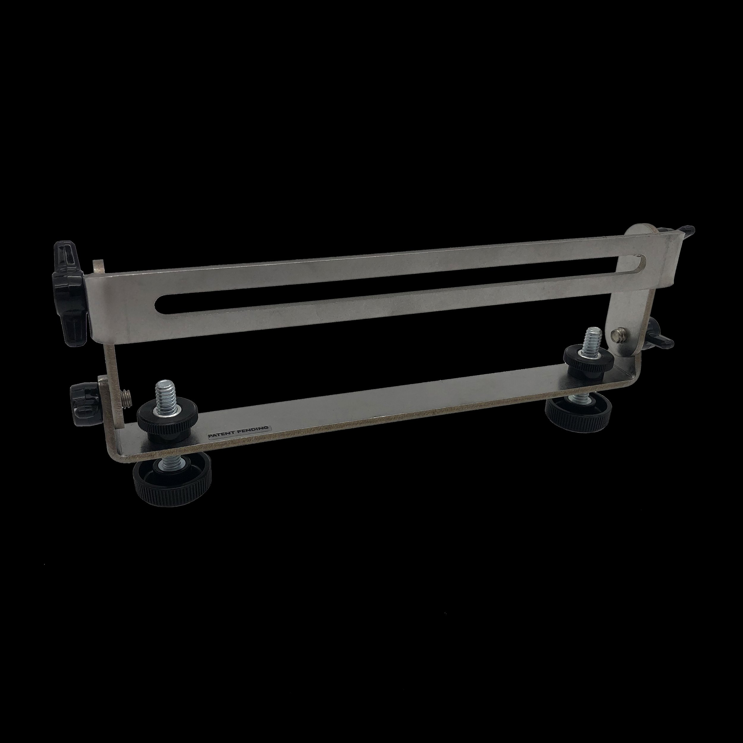
The Universal Bracket is height-adjustable, and has over 360° of tilt-adjustability. This allows you to attach the Motor Box to your equipment at any angle. The stock height-adjustable legs can be replaced with Extension Legs for mounting the Motor Box to effects pedals on the floor or some amplifiers with horizontal, top-facing controls. All adjustments to this bracket can be made without using any tools.
The Mounting Brackets


The “T” Bracket is a sleek solution for most amplifiers with vertical, front-facing controls. It can be orientated to accommodate top or bottom mounted chassis. The vertical slot allows for height adjustment of the Motor Box and the slot on the base is for feeding the connection cable through. It has a rubber pad on both the top and bottom of the base so it will never damage your equipment, regardless of it’s orientation. This bracket is ideal if the front of your amplifier head sits flush with the front of the speaker cabinet leaving no room for the Universal Bracket to rest on.


The connection from the foot controllers to the Motor Box is made with a standard 3.5mm TRS (stereo) cable. This is just a common headphone or “auxiliary” cable. The power adapter for both foot controllers is UL certified, 9V, 1.0A, with a center-negative polarity.

